VANAIRE WASTEWATER SYSTEMS
Resources for existing installations
We’re continually building resources for our customers to extend the life of thier investment in a VanAire Wastewater System. Check back for additional content or contact us with any questions.
We’re continually building resources for our customers to extend the life of thier investment in a VanAire Wastewater System. Check back for additional content or contact us with any questions.
FAQs
- Is your aeration pump feed isolation valve fully open? If not fully open valve
- Is your MicroAire DAF® Aeration unit on? If No, turn unit on
- Is aeration pump pressure adequate?
- Close breakout valve(s) or if equipped close isolation valves after the breakout valves and vent lines and read first pressure gauge on header:
- If pump pressures read as stated below, then pump is OK – move to next step
- 15-50 GPM = approximately 105 psi
- 75-100 GPM = approximately 100 psi
- 150-750 GPM = approximately 115 psi
- If pump pressures are low, adjust pump side plate for open impeller pumps, following instructions from the Sulzer pump manual:
- Loosen the hex nuts of the adjusting screws.
- One by one, turn each adjusting screw counterclockwise until the sideplate touches the impeller. Then turn the adjusting screws clockwise 1/3 turns to obtain a 0.5 mm (0.02 in) clearance between the sideplate and impeller.
- After the adjustment, tighten the hex nuts, whereby the adjusting screws will be locked. The adjusting screw must not turn during tightening.
- By turning the coupling by hand, check that the pump can rotate freely.
- The sideplate can be adjusted altogether 3 — 4 mm (0.12 — 0.16 in) towards the impeller. If further adjustment is needed, change the impeller and sideplate to keep the right clearance.
- If pump pressures are low and pump adjustment is correct, see Breakout Valve section for torn diaphragms.
- If pump pressures read as stated below, then pump is OK – move to next step
- Is air compressor on? If No, turn compressor on
- Is air pressure at 140 psi (minimum) at regulator on aeration unit? If low adjust regulator. If still low what is capability of compressor? Compressor should be able to supply 140-160 psi.
- Filter and Regulator
- Is air coming out of the filter and regulator at a minimum 140PSI?
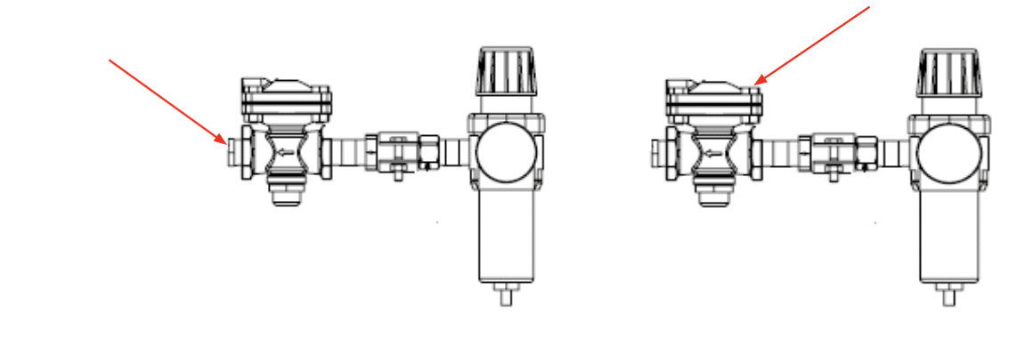
- Cash Valve
*** Note: For aeration units starting in 2017, the Cash Valve was moved to a position on the header of the aeration unit. The inline pressure in the header now opens the cash valve.
For aeration units prior to 2017:
- Turn off aeration unit, turn down air pressure to 40 PSI on regulator or less to a safer amount.
- Then remove bottom blue hose coming out of the Cash Valve as indicated below.
- Turn aeration unit on. There should be air coming out of the hole, you disconnected the hose from.
- If no, turn off aeration unit, remove both blue hoses to the Cash Valve. Check both hoses for obstructions. Remove the top of the Cash Valve (indicated below) and verify that the top is not plugged with sediment between the diaphragm and cap of valve.
- Press down in the center of the Cash Valve to verify the spring is still intact and is not broken. If there is no evidence of failure the Cash Valve may be worn out.
- Before connecting the blue lines back up, disconnect them from the rotameter and pump/header and make sure they are not plugged.
- Is the rotameter ball in the green zone?
- Adjust Rotameter by turning knob on face, turn clockwise to increase air flow, turn counter clockwise to decrease air flow
- Unable to adjust rotameter
- Disconnect the blue hose out of the air injector that comes from the top of the rotameter.
- Making sure the regulator is adjusted to 40psi or less, turn on aeration unit and check to see if there is air coming out of the hose. Turn dial on the front of rotameter if needed to let air through.
- If no air, remove the blue hose from the rotameter and inspect it for a plugged line. Remove Legris fittings, then visually look at the rotameter to see if there is any obstructions. You may need to take it apart and clean it to find the blockage.
- Air Injector
** Note: For Aeration units starting in 2016, the aeration unit should have a check valve placed in #1 below. These injectors with check valves will not have a white plastic bullet (2). But, you should still remove the check valve and clean the inside of the injector body.
- The air injector is threaded on the back side of the header or on the opposite side of the static mixer pressure gage. The aeration unit must be off and the water drained down before removing it.
- To remove the air injector(s), loosen the injector nut (3), then unscrew the air injector from the half coupling. Once removed, take off the Legris fitting and then unscrew the air injector tube (4).
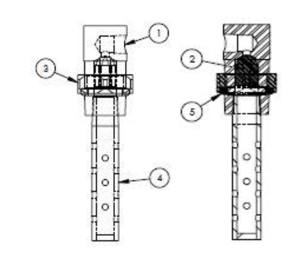
- The air injector tube (4) must be cleaned out, including all holes on the sides.
- From the air injector tube side of the air injector body (1) there is a white plastic bullet (2)**(see note above) that fits inside. This also must be removed and cleaned along with the inside of the body itself. You should be able to put water or air in one hole and get it out of the other. The plastic bullet is designed to keep water out of the rotameter, prior to installation of the check valve noted above. Most of the causes for lack of air, is no maintenance on the air injector.
- Breakout Valves
- The last area to check for lack of air is the diaphragms on the breakout valves. There may be a tear or hole in a diaphragm. If this is the case, there should have been a noticeable change in the differential pressure on the gages of the saturation tank, then what is recommended or the normal operating range. You also need to check the weep hole in the bonnet for drainage of water to locate or find a bad diaphragm.
- If there is more than one saturation tank you should see better pressure with a good diaphragm than a bad one. That will give an indication which diaphragm to change. A tear or hole would allow more water not bubbles to run through the breakout valve into the tank causing a turbulence of water with no bubbles. The differential pressure needs to be there to create the micro bubbles.
- Is differential pressure between pump gauge and saturation tank gauge within range per manual?
- Adjust breakout valve and/or adjust vent to 30% open
- Unable to adjust differential pressure check BOV for leaking, damage to BOV is evident by fluid dripping from seep hole in valve casing
- Unable to adjust differential pressure check gauges are functioning properly by closing BOV(s) and closing vent. Gauges should be close to equal, if not may need to clean behind the gauge as the opening to the diaphragm could be clogged. Carefully clean as diaphragm is fragile and can be punctured if not using a soft item to clean the area. If diaphragm is not clogged replace gauge with new gauge assembly.
Each application is a little different but normally tighten BOV until the bonnet feels snug and then back out approximately a ¼ turn. Pressure differential should be around (15-35) site dependent.
Recommended air pressure is 140-160 psi.
The rotameter only sees the total water line pressure during operation which is 80-90 psi. VanAire requires 140psi minimum air pressure to obtain the smallest bubbles. Air travels from the air filter that has a metal bowl rating of 250psi, through the air regulator (regulator should be set to 140psi), gauge on the air regulator is 0-300psi, air then travels to the cash valve mounted on the header piping (cash valve MAWP is 250psi), once the pressure in the header is high enough it moves the valve in the cash valve to allow air to the rotameter (rotameter MAWP is 100 psi), air travels through the rotameter to the check valve (MAWP 580psi) and through the injector. Since the header pressure is lower than the air pressure the pressure in the aeration system equalizes to the header pressure. So, the rotameter is only seeing 90psi. The only way the rotameter could see higher allowable pressure is if the system is deadheaded. One could deadhead the pump, but the check valve will stop the pressure to the rotameter. The air would need to be left on while trying to trouble shoot the pump to reach a higher pressure.
The air regulator needs to be at 140psi so that we are below the maximum of the blue hose (MAWP stated below). All other items are rated higher than the maximum pressure of our standard air compressor can produce. The diaphragm gauges in the water system lines only see a maximum pressure 80-90 psi and 60-70 psi. If someone were to deadhead the system and left the air on only then these gauges and rotameter could see a higher pressure of 140psi. Also, someone would have to set the air regulator higher than allowable.
Blue hose = MAWP 150psi
Legris fittings = MAWP 290psi
Cash valve = MAWP 250psi
Air gauge = 0-300psi
Diaphragm pressure gauges = 0-160psi
Loosen the bolts holding the pillow block bearings to allow movement of the chain sprocket shaft. Then turn the nuts on the adjuster threaded rods to move the bearings thereby moving the shaft and sprockets and tensioning the chain. Be sure to adjust both adjusters the same amount so both chains are tensioned the same and the skimmer flights remain perpendicular to the walls of the DAF Clarifier.
Slack in chain between flights should be approximately 3/4-inch to 1-inch
When flights running, as flight returns from drive sprocket the flight should tip approximately 45°
Check shaft alignment by making sure shaft is perpendicular to the side plates and the shafts are parallel to each other. Take measurements from corner to opposite corner to check if shafts are square to each other. Adjust shafts as needed by following “How to adjust skimmer shafts”.
Check sprocket to see if they are moving on shaft – check for clean marks near the sprocket to show that it moved from the original position
Shaft collars have been installed on prior DAFs because the sprocket hubs were not made to allow proper clamping
There is a chemical attack which is causing swelling of the rubber. We recommend changing to Viton or High temperature Silicon.
The rubber seal strips should be replaced when they no longer remove floated solids.
Replacement of the strips is done by loosening all the bolts that hold the stainless retaining bracket to the Skimmer Flight. Once loose, pull the old strips out and insert new strips so that they overhang each end by 1-1/2″.
Skimmer Flight speed adjustment can be adjusted by either the potentiometer on the panel cover or adjust using the VFD in the panel to limit speed adjustment of the pot.
When to increase or decrease flight speed is dependent on customer process. If float is being seen in the clearwell, recommend increasing speed and possibly decrease flight delay (See below for adjusting delay). Decrease flight speed when float is very minimum on flights and very little float going into the float hopper.
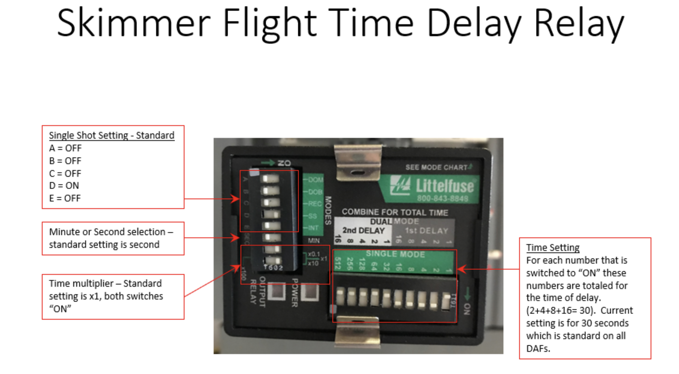
How do I adjust my Flight Delay? Ask what their current settings are at compare the settings to the “Skimmer Flight Time Delay Relay” instructions below. Standard setting is 30 seconds. To increase delay, add more time by switching on 32 or to decrease time, switch off times.
- Float auger speed adjustment can be adjusted by either the potentiometer on the panel cover or adjust using the VFD in the panel to limit speed adjustment of the pot.
- Bottom auger speeds adjustment can be adjusted by either the potentiometer on the panel cover or adjust using the VFD in the panel to limit speed adjustment of the pot.
- Mixer speeds adjustment can be adjusted by either the potentiometer on the panel cover or adjust using the VFD in the panel to limit speed adjustment of the pot.
The pressure switch is there to tell the control panel to shut off the pump and not over pressurize the progressive cavity pump. If the switch was not there and a valve was closed and the pump was on, this will cause damage to the pump and the pump would not be warrantied
If the pump was on and pumping nothing then the temperature switch would trip because of heat and shut off the pump. This is to prevent the pump from overheating if it were in a run dry for too long.
Call E&H Tech Support @ 888-363-7377
CONTACT US
Start Your Project Today
Lead times on Wastewater projects can be significant. Get started on your upcoming job with the VanAire team and we’ll start the planning process, together.
Lead times on Wastewater projects can be significant. Get started on your upcoming job with the VanAire team and we’ll start the planning process, together.